Principle of Operation
Magnetic Flux Leakage Detection
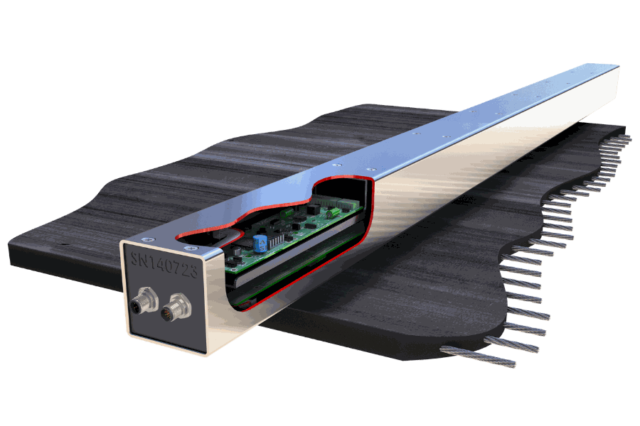
Two permanent magnet arrays (conditioning heads) are installed above and below the belt with matching magnetic poles facing each other. As the belt passes between them, the steel cords are selectively magnetised. Any discontinuity in a cord — even individual filaments — produces an external magnetic field (magnetic flux leakage). The downstream sensor Belt Scanner detects this leakage via multiple pick-ups dispersed across the belt width.
01
Condition
Two magnet bars (one above, one below) magnetise the steel cords as the belt passes between them. Installed 35–50mm from the belt surface. Distance decreases for higher ST ratings.
02
Detect
The sensor Belt Scanner reads the magnetic signature of each cord. Damaged cords produce flux leakage anomalies. Data is processed and stored in non-volatile memory inside the Belt Scanner.
03
Analyse
Scan data is downloaded via USB to the laptop. BSMF Data Viewer and Belt Analysis software identify damage type, severity, and longitudinal position using tachometer data. Magnetic fingerprint comparison enables splice trending.
Magnet Safety Warning
The magnet bars produce a very strong magnetic field. No magnetically sensitive devices (credit cards, mobile phones, watches) should be allowed within 3.0 metres. Never allow a magnet bar to contact the belt directly during installation or removal — this may induce a magnetic signature in the belt carcass. Note: the signature typically corrects over multiple belt revolutions. When not in use, separate the two magnet bars with 25mm² wooden blocks and tie together.
Damage Detection
What It Detects
Broken cords — complete wire breaks within a cord
Rusted / corroded cords — corrosion-induced magnetic changes
Kinked cords — vertical plane deformation from belt handling damage
Fatigued cords — filament discontinuity from plastic deformation and ductile failure
Missing cords — absent cords in the belt cross-section
Splice anomalies — deterioration detected via magnetic signature comparison
Comparison
Fixed vs Portable
| Capability | Fixed BSMF | Portable BSMF |
|---|
| Conveyors scanned | One (permanent installation) | Multiple (moved between conveyors) |
| Belt stoppage | Not required | Not required |
| Power source | 24VDC / 110VAC / 240VAC | 5VDC via USB (laptop) |
| Remote scanning | Yes — run scans remotely at any time | No — operator on-site with laptop |
| Programmed Parking | Yes | No |
| DED (belt stop protection) | Yes — 24/7 automated belt stop | No |
| Belt synchronisation | Yes — improves data repeatability | No |
| Scan data repeatability | Higher (fixed position, belt sync) | Good (varies with installation) |
| Installation | Permanent — 2-day commissioning | Site-specific mounts per conveyor |
System Components
What’s Included
Sensor Transducer
316 SS, IP67, multiple pick-ups, non-volatile memory
2× Magnet Bars
316 SS, permanent magnet conditioning heads, span full belt width
USB-RS485 Adapter
ABS IP68, powers Belt Scanner via laptop USB, data connection
Tachometer
Probe + button magnet for idler roller, longitudinal position tracking
Analysis Software
BSMF Data Viewer + Belt Analysis — data capture, magnetic fingerprint, trending
Documentation
Full installation, wiring, and operation manuals (PDF)
Specifications
Technical Data
| Parameter | Value |
|---|
| Belt Type | Steel Cord |
| Contact | Non-contact |
| Transducer Construction | 316 Stainless Steel, IP67 |
| Transducer Size | 80 × 80 × L mm (per belt width) |
| Transducer Weight | 9 kg per metre length |
| Magnet Bar Construction | 316 Stainless Steel, IP67 |
| Magnet Bar Size | 40 × 40 × L mm (per belt width) |
| Magnet Bar Weight | 9 kg per metre length (each) |
| Magnet Distance | 35–50mm from belt surface |
| USB Adapter Construction | ABS Plastic, IP68 |
| USB Adapter Size | 135 × 65 × 45mm |
| USB Adapter Weight | 1.3 kg |
| Power Source | 5VDC via USB (laptop / PC) |
| Operating Temp | -25°C to +70°C |
| Storage Temp | -40°C to +80°C |
| Humidity | 5–95% RH |
Deployment
Installation
Magnet bars: Installed above and below the belt with matching poles (North) facing each other. Must span full belt width plus wander allowance. Higher ST rating = shorter distance to belt surface.
Transducer: Located in a flat belt path with minimal flap and droop. Away from electrically noisy locations (drive motors, switchgear). Can be positioned above or below the running belt.
Tachometer: Sensor probe mounted on an idler roller frame, excited by a button magnet glued to the idler end disc. Confirm no residual magnetic signatures on the end disc before installation. Measure and record roller diameter.
Maintenance
Ongoing Requirements
The Belt Scanner MF Portable requires very little maintenance. Keep the system free from product build-up. No user-serviceable components inside the Belt Scanner or USB adapter. Always replace dust caps on connectors after use. Avoid standing on connectors.
Applications
Where It’s Used
Multi-Conveyor Sites
Fleet Assessments
Baseline Belt Surveys
Mining Operations
Coal Handling Plants
Port Facilities
Overland Conveyors
Splice Condition Trending
Also available on a rental basis with optional Beltscan data analysis service — remote scan review and monthly condition reporting.