

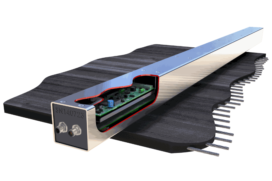
Why Belt Scanner MF Fixed?
Identify developing cord and splice deterioration before it becomes a failure.
Monitor the steel cord belt continuously while the conveyor remains in operation.
Integrate DED and Programmed Parking with the site PLC for automated responses.
Belt Scanner MF — Fixed
Permanent steel cord belt condition monitoring
Continuous full-width magnetic condition monitoring for steel cord conveyor belts. Detect developing cord and splice damage, track change over time and automatically respond to critical events.
The fixed system is configured around your belt width, installation arrangement, control integration and site monitoring requirements.
Supplied directly by Beltscan Systems or through authorised regional partners.
Belt Scanner MF Fixed — Key Data
Systems are engineered to the conveyor rather than selected from a size range. The figures below are the fixed characteristics of the system; belt-specific parameters are confirmed during application engineering.
Belt & scanning
| Belt type | Steel cord |
| Belt width | Engineered to belt width plus the required wander allowance |
| Belt speed | Application engineered — no fixed scanner limit specified |
| Steel cord rating | Application engineered — no fixed ST rating specified |
| Monitoring | Continuous condition monitoring and DED, with the belt running |
| Belt scans | Acquired for condition analysis and historical comparison |
| Sensing | Full-width magnetic flux condition monitoring |
| Contact | Non-contact |
| Scanner standoff | 35 mm nominal · less than 50 mm maximum |
System, power & environment
| Communications | Ethernet TCP/IP · Modbus TCP |
| Control outputs | 4 × Form C, 5 A 240 VAC — Healthy · HALT / DED · Sync Lock · Park |
| Power | 24 VDC · 110 VAC · 240 VAC |
| Operating temperature | −25 °C to +70 °C |
| Storage temperature | −40 °C to +80 °C |
| Humidity | 5–95% RH |
| Scanner construction | 316 stainless steel |
| Typical conveyor shutdown | Approximately 1 day for a prepared installation |
| Belt modification | None |
One Complete Permanent Monitoring System
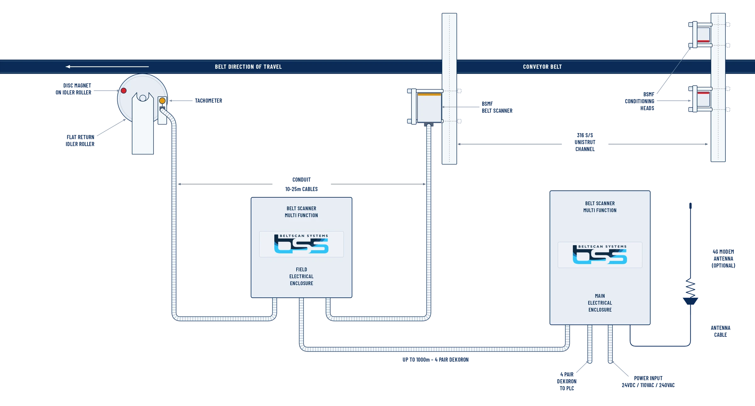
The Belt Scanner MF Fixed is supplied as a complete engineered monitoring system — not simply a sensor. The scanner, magnetic conditioning heads, tachometer, electrical enclosures, communications and control interfaces work together to provide repeatable permanent belt condition monitoring.
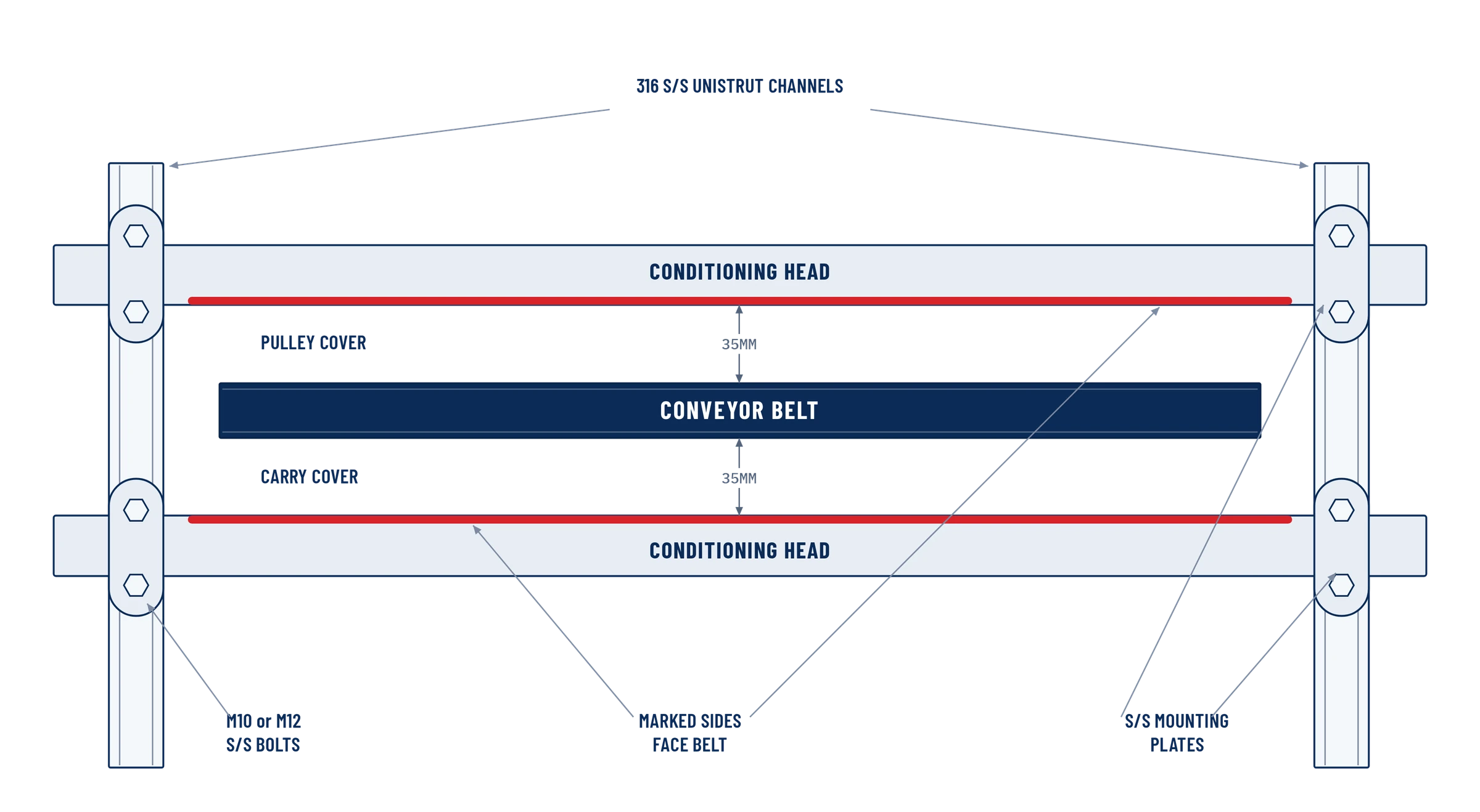
Two permanent magnetic conditioning heads, one above and one below the belt, establish the magnetic condition of the steel cords.
The running belt passes between the conditioning heads and on to the scanner. Nothing is embedded, bonded or cut into it.
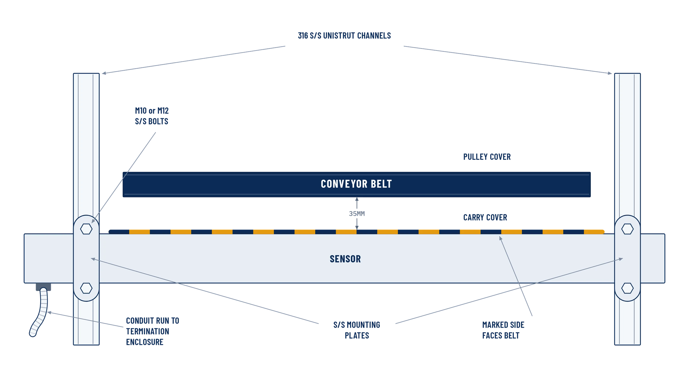
A full-width non-contact scanner reads the magnetic signature across the whole belt width as it passes.
Field termination for the scanner, conditioning heads and tachometer cabling on the conveyor structure.
Control electronics, data storage, the Belt Signature File, DED evaluation and the relay outputs.
Site control integration — hard-wired relay outputs for Healthy, HALT/DED, Sync Lock and Park, plus Modbus TCP data.
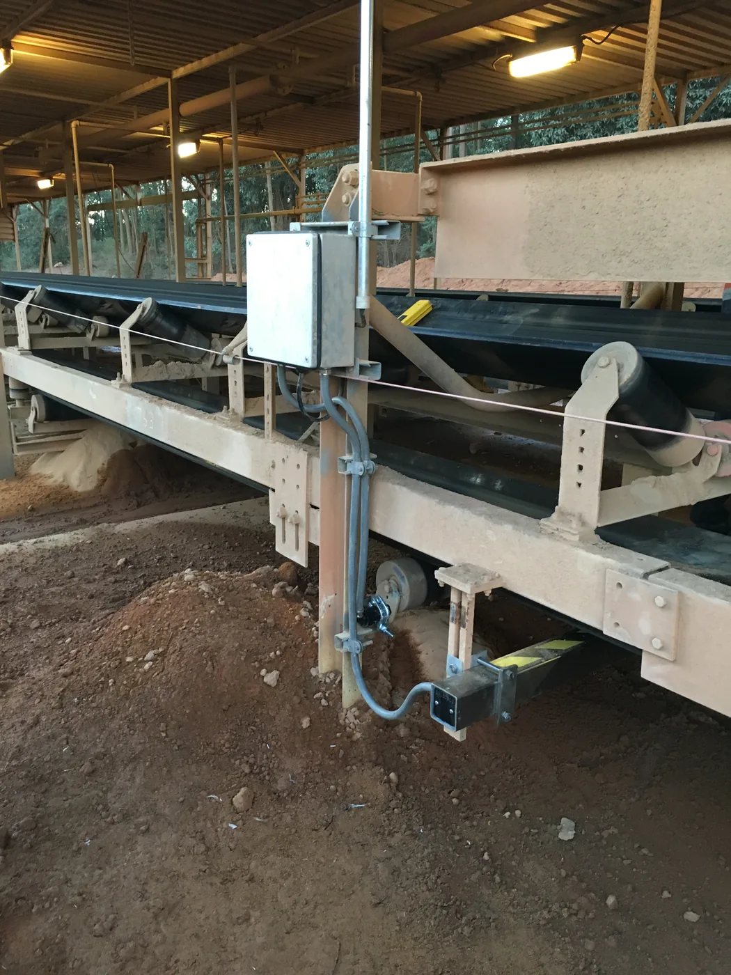
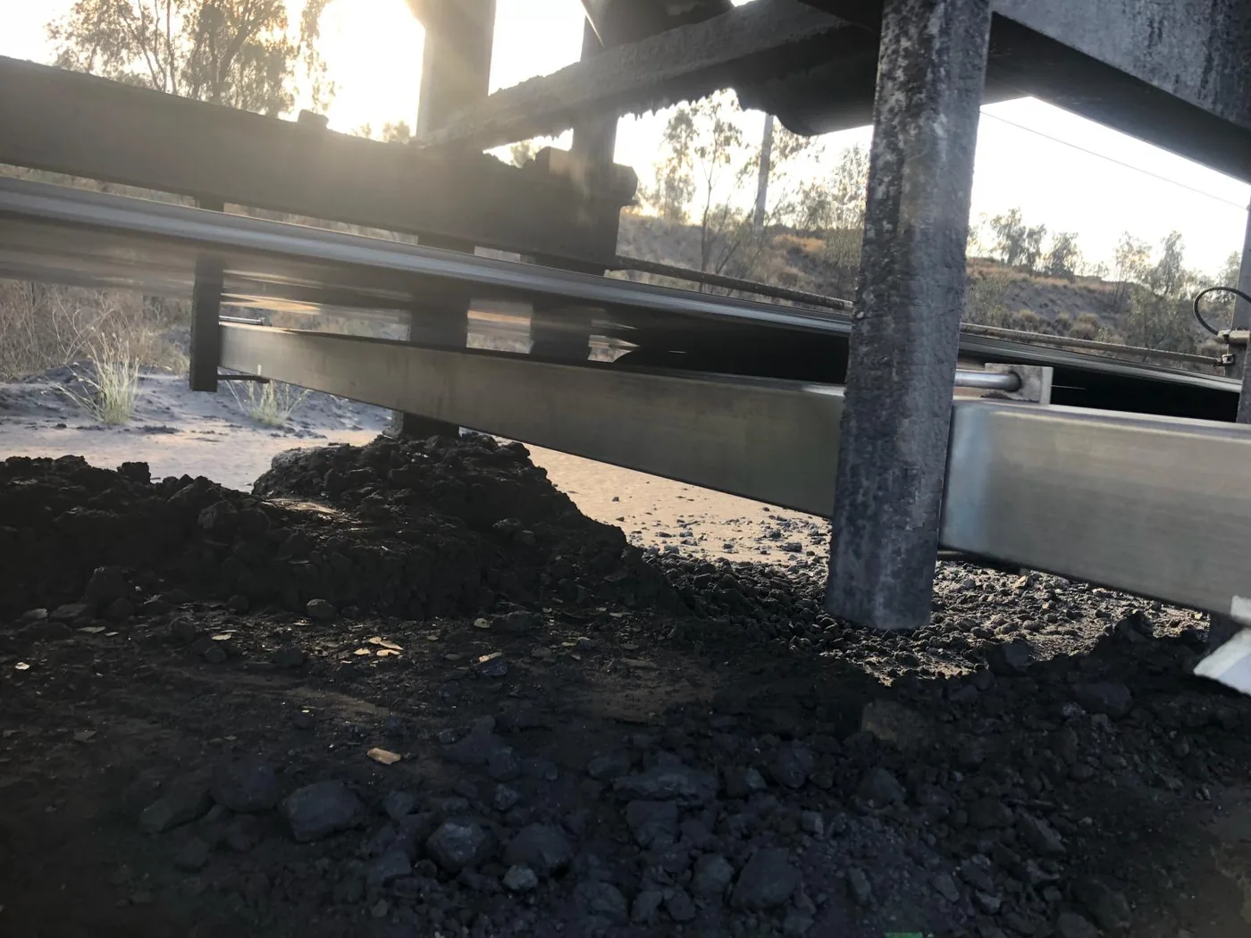
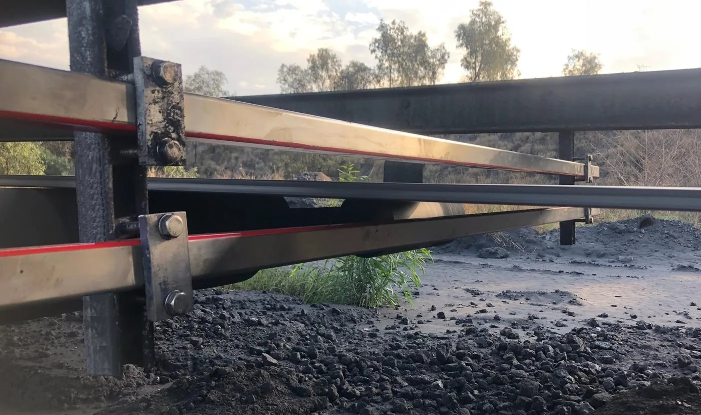
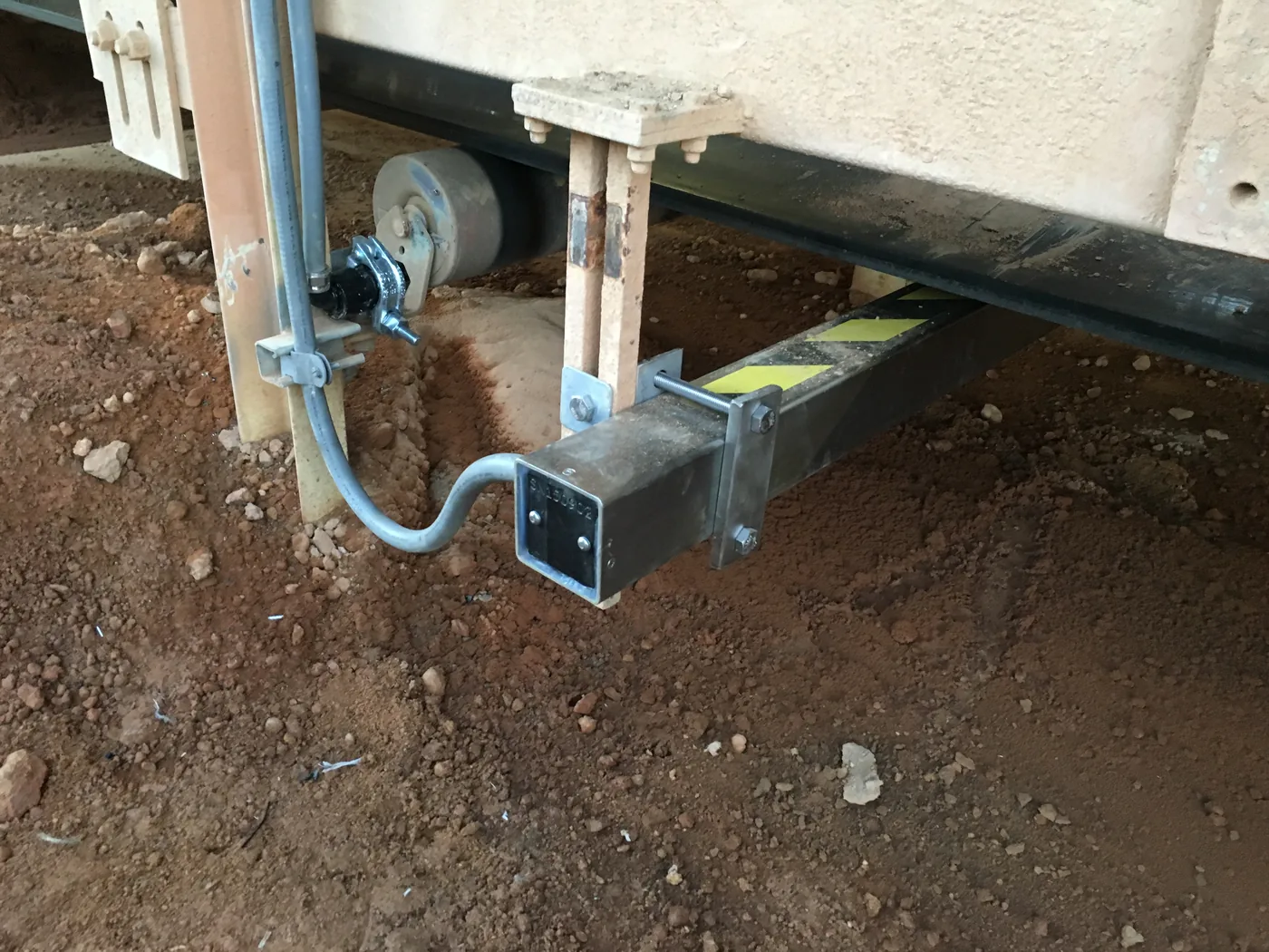
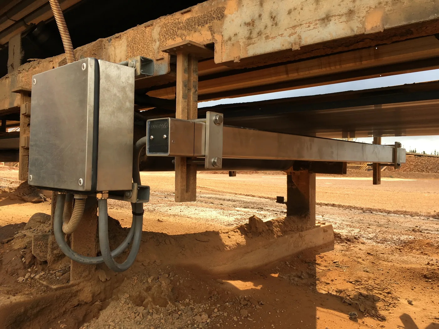
Engineered for Real Conveyor Installations
Independent of Belt Manufacturer
Belt Scanner MF Fixed is configured to the steel cord belt and conveyor application rather than tied to a particular belt OEM.
This makes the system suitable for new installations and retrofit applications across steel cord belts from different manufacturers.
Nothing is embedded, bonded or cut into the conveyor belt. The Belt Scanner, conditioning heads and tachometer mount to the conveyor structure.
Existing belts can be brought under monitoring without waiting for a belt change, and the system stays with the conveyor when the belt is replaced.
Supporting steelwork, cable routing and electrical/network preparation can be completed in advance. A prepared installation typically requires approximately one conveyor shutdown day for final mechanical installation, alignment and connection. Actual duration depends on the conveyor, access and the extent of preparation completed beforehand.
What Belt Scanner MF Detects
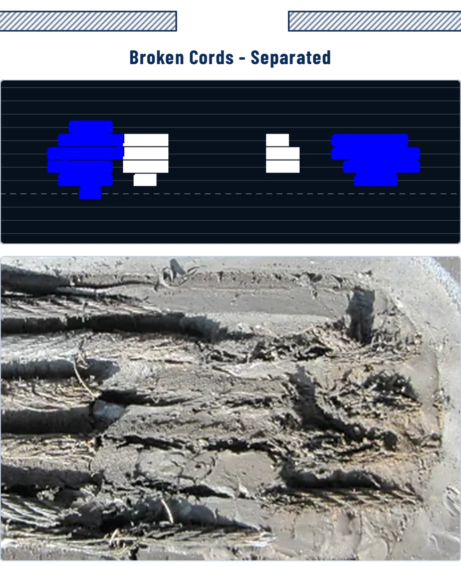
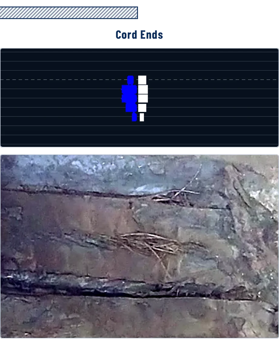
Magnetic Flux Leakage Condition Monitoring
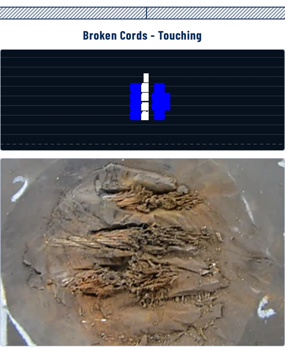
Belt Scanner MF Fixed uses established magnetic condition monitoring principles. The steel cords are magnetically conditioned, the resulting field is read across the full belt width, and the result is compared with what the belt looked like before.
Condition
Permanent magnetic conditioning heads, one above and one below the belt, establish the magnetic condition of the steel cords as the belt runs.
Detect
The full-width non-contact Belt Scanner detects magnetic flux leakage associated with cord discontinuities and changes in the steel cord carcass.
Compare
Current scan data is compared with historical data and the stored Belt Signature File to identify developing change rather than a single snapshot.
Act
DED can initiate conveyor shutdown through the dedicated hard-wired HALT interface. Programmed Parking can position a nominated splice or belt location for inspection.
Disastrous Event Detection & Programmed Parking
When the system is synchronised to the belt, DED continuously evaluates live belt condition against the stored Belt Signature File. Where configured trip criteria are exceeded, the system activates the dedicated HALT output.
Trip criteria are set during commissioning and can be adjusted afterwards. The Belt Signature File is refreshed after analysis so that known, accepted damage does not repeatedly trip the system.
A nominated splice or identified belt location can be automatically positioned at a predefined maintenance location, reducing manual belt inching and positioning time.
Parking depends on the tachometer input for belt position, and on the Park relay output to the site control system.
Belt Scanner MF Fixed supports Ethernet TCP/IP and Modbus TCP for plant integration. Four dedicated hard-wired Form C relay outputs are provided — Healthy, HALT/DED, Sync Lock and Park.
Critical DED belt-stop functionality uses the dedicated hard-wired HALT relay into the site PLC/SCADA or conveyor control circuit. It does not rely solely on the network communications path.
System operating normally.
Belt-stop command on a DED trip. Hard-wired.
Scan synchronised to belt position.
Programmed Parking position reached.
4 × Form C changeover relay outputs, rated 5 A 240 VAC. Configuration and data are carried over Ethernet TCP/IP and Modbus TCP.
Installation at a Glance
Detailed scanner positioning, conditioning-head clearances, tachometer mounting, electrical connections and PLC requirements are provided in the installation documentation.
View Detailed Installation Requirements
MechanicalMechanical Installation Details
| Belt Scanner | 316 stainless steel. 80 × 80 × L mm, 15–17.5 kg/m. Marked sensing side faces the belt. |
| Scanner standoff | 35 mm nominal from the belt surface. Beyond 50 mm the magnetic signature weakens and the quality of the analysis falls with it. |
| Conditioning heads | 2 × permanent magnetic conditioning heads. 316 stainless steel, 40 × 40 × L mm, 7–7.5 kg/m each. |
| Conditioning head standoff | 35 mm nominal belt standoff, matched between the two heads. A difference greater than 10 mm can degrade the magnetic signature. |
| Separation | Conditioning heads a minimum of 1000 mm from the scanner. Tachometer a minimum of 1000 mm from the scanner, so their own fields do not reach it. |
| Tachometer | Non-contact, with a 10–30 mm target gap to a standard 20 × 3 mm disc magnet. Provides longitudinal belt position and speed. |
| Mounting | Typical installation uses 316 stainless Unistrut, stainless mounting plates and M10/M12 stainless fasteners. |
| Belt path | A flat return belt path is preferred, with minimal belt flap or droop through the scanning position. |
| Conveyor shutdown | Required for mechanical installation of the conditioning heads and scanner frame. Approximately 1 day for a prepared installation. |
| Belt modification | None. Nothing is embedded in, bonded to or cut into the belt. |
| Permanent fixtures | Conditioning heads and scanner frame remain in place. |
Belt SpeedTachometer / Belt Speed Input
| Tachometer | Mounted to an idler roller mount, within 10–30 mm of its target magnet. The mount design is site-specific and is the customer's responsibility. Standard magnets are 20 × 3 mm discs. |
The tachometer synchronises the scan to belt position. Without it, events have no reliable location, scans can’t be compared point for point, and neither Programmed Parking nor DED can operate.
ElectricalElectrical and PLC Connections
| PLC required | Required for alarm integration, automated belt stop and Programmed Parking. The system runs without one for monitoring and reporting only. |
| Control connection | 4 × Form C changeover relay outputs rated 5 A 240 VAC: Healthy, HALT, Sync Lock and Park. Configuration and data are over Ethernet TCP/IP. |
| What power is required? | 24 VDC, 110 VAC or 240 VAC for a fixed system. |
CommissioningCommissioning Requirements
| Installed by | Site personnel, following the supplied wiring and mounting documentation with remote Beltscan support. |
| Commissioning | Carried out remotely with Beltscan support. |
| Training | Included with commissioning. |
| Laptop required | Yes, for configuration and offline analysis. |
| Internet required | Not for local operation. Required for the online portal and remote support and reporting. |
Plant Integration
Communications & power
| Network | Ethernet TCP/IP |
| Fieldbus | Modbus TCP |
| Site connectivity | Connects to the site network for configuration, data and status |
| Remote connectivity | Available where configured and where the site communications environment allows |
| Power | 24 VDC, 110 VAC or 240 VAC |
Hard-wired outputs & enclosures
| Relay outputs | 4 × Form C changeover, rated 5 A 240 VAC |
| Healthy | System operating normally |
| HALT / DED | Hard-wired belt-stop command to PLC/SCADA or conveyor control circuit |
| Sync Lock | Scan synchronised to belt position |
| Park | Programmed Parking position reached |
| Main Electrical Enclosure | 600 H × 400 W × 200 D mm |
| Termination enclosure | 300 H × 300 W × 150 D mm |
Enclosure dimensions are nominal and may vary with project scope. Cable routing, glanding and supply arrangements are confirmed during application engineering.
Hardware Detects It.
Beltscan Helps You Understand It.
Every Belt Scanner MF system includes the software suite and a secure online portal. Acquired belt scans are retained and searchable, so condition can be compared across successive scans rather than read one scan at a time.
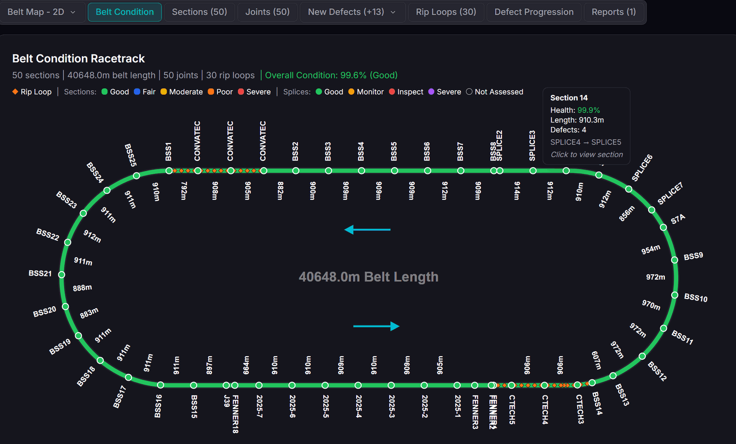 Belt condition overview
 Full belt map
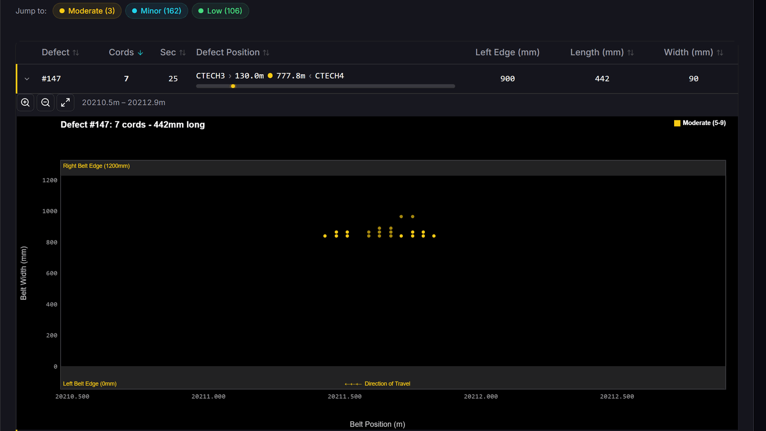 Defect detail & reporting
Don't want another monitoring system your team has to interpret?
Beltscan specialists can remotely review your scan data and provide scheduled condition reports identifying new damage, developing events, splice changes and maintenance priorities. This is a separate service, quoted and provided only where the commercial package includes it — the system software itself is supplied with every system.
Ask about scheduled condition reporting →Proven Permanent Monitoring
Belt Scanner technology has been installed on conveyors across Australia, Asia, Europe, North America and South America, in mining, alumina, steel, coal and bulk materials handling operations.
Western Australian alumina operation
Continuous operational service
Additional reference installations are available on request. Read the Western Australia alumina case study →
What’s Included
Every Belt Scanner MF Fixed system is supplied with the hardware and software below. Services and site works depend on the commercial scope of the individual quotation.
Supplied with every system.
- BSMF full-width Belt Scanner
- 2 × magnetic conditioning heads
- Main Electrical Enclosure
- Field / Termination Electrical Enclosure
- Non-contact tachometer and target magnet
- Relevant mounting brackets
Supplied with every system. First-year licence included.
- System software — scanner communication and configuration
- Scan acquisition, viewing and analysis
- Online portal access and reporting
- Data download and export
From year two an annual renewal covers the complete Belt Scanner MF software and reporting suite.
Confirmed per quotation, not automatically included.
- Engineering documentation
- Commissioning support
- Operator training
- Remote engineering support
- Optional specialist condition analysis — separate service
Not included unless the quotation states otherwise: supporting mounting steelwork, field cabling and containment, installation labour, site network or remote connectivity provision, and ongoing specialist analysis services.
Each Belt Scanner MF – Fixed system is quoted for the application. Final configuration depends on belt width, conveyor arrangement, control integration, destination and site-specific installation requirements.
Projects are supplied directly by Beltscan Systems or through authorised regional partners.
Engineering Documentation
Published documents download directly. Documents marked for request are issued against a project — tell us the conveyor and we will send the current revision.
Specifications and operating requirements for the fixed system.
Request the datasheet →System overview and capabilities.
Download PDF →Technology, DED and Programmed Parking.
Download PDF →Mechanical, electrical and commissioning requirements.
Request the guide →General arrangement and mounting requirements.
Request the drawing →Power, Modbus TCP, PLC/SCADA and the relay interface.
Request the guide →System Overview
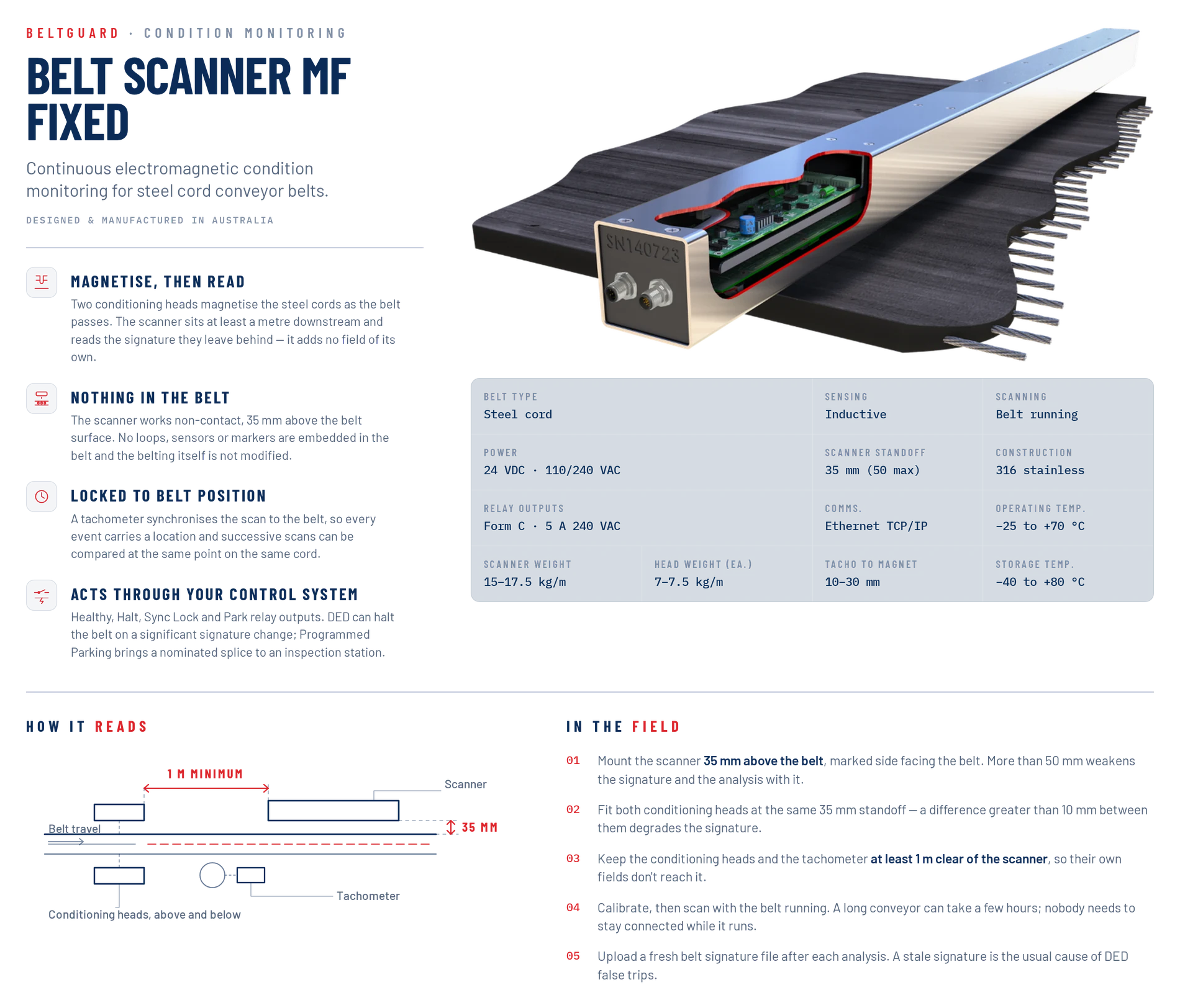
Technical Articles
Need CAD drawings, a general arrangement marked up for your conveyor, or a project-specific technical submission?
Request Engineering InformationIs Belt Scanner MF Fixed Right for You?
- Operate steel cord conveyor belts
- Run a conveyor critical enough to justify permanent monitoring
- Want cord and splice deterioration identified before failure
- Want continuous monitoring rather than periodic inspection
- Want alarms and automated response integrated with your PLC
- Have several steel cord conveyors to cover
- Find periodic scanning sufficient
- Don't need PLC integration or automated belt stopping
- Want one scanner that moves between belts
Tell us about your conveyor and we’ll recommend the right system.
Frequently Asked Questions
Engineering & Procurement Information
Supporting detail for the people who have to approve, connect and live with the system — the figures an approver will ask for, how the data behaves on your network, what ownership involves, and what your procurement team needs. Open a section to read it.
Business CaseBuilding the Business Case
The engineer who wants the system is rarely the person who approves it. These are the figures an approver will ask for — worth assembling before the conversation.
Steel cord belting, freight and installation for the affected conveyor
Hours to source, transport, splice and recommission after a failure
Throughput value or contractual exposure for each hour the conveyor is down
Expedited freight, out-of-hours labour, contractor mobilisation
Periodic inspection labour and the shutdowns it requires
Spillage clean-up, structural damage, safety and environmental reporting
Beltscan does not publish return-on-investment claims. The figures above are yours — we'll help you populate the system side of them.
IT and OTData, Network and IT
| Network position | Control hardware sits on the site network and communicates with the PLC over Modbus TCP. |
| Outbound traffic | Nothing leaves site for local operation. Portal and remote reporting use an outbound HTTPS connection only. |
| Control path | Only the alarm and stop signals you configure at the PLC. The portal has no control path to site equipment. |
| Data ownership | Scan data is yours and can be exported at any time. |
OwnershipLiving With the System
| Calibration | Sensitivity is calibrated at commissioning and checked against the live display. The procedure is in the operator's manual and is normally done with remote Beltscan support. |
| Belt replacement | A new baseline scan is established for the new belt or splice, and trending continues from that baseline. |
| Communications loss | Local belt monitoring and the hard-wired HALT output are independent of the remote network connection. Remote access, data retrieval and reporting resume when the connection does. |
| Maintenance | Visual inspection on a regular basis to confirm all mounts are secure, and a light hose down to keep the system free of product build-up. |
| Belt signature file | A fresh belt signature file should be generated and uploaded after each analysis. A stale signature is the usual cause of DED false trips. |
ProcurementFor Your Procurement Team
| Supplier | Beltscan Systems Pty Ltd, ACN 614 321 309, PO Box 10457, Southport QLD 4215, Australia |
| Commercial supply | Quoted by Beltscan Systems or the authorised regional partner for the project location. |
| Scanner construction | 316 stainless steel, 80 × 80 mm section. Length varies with belt width. |
| Conditioning heads | 316 stainless steel, 40 × 40 mm section, one above and one below the belt. |
| Weight | Scanner 15–17.5 kg per metre. Conditioning heads 7–7.5 kg per metre each. |
| Operating temperature | −25 to +70 °C, 5–95% RH |
| Storage temperature | −40 to +80 °C, 5–95% RH |
Also in Belt Guard Range
Portable electromagnetic scanner for multi-conveyor steel cord monitoring via slide-in tube assemblies.
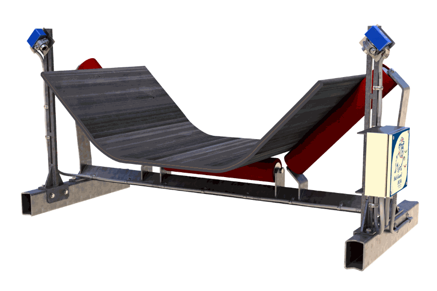
Longitudinal rip detection for fabric, PVC and steel cord belts, from continuous belt width monitoring.
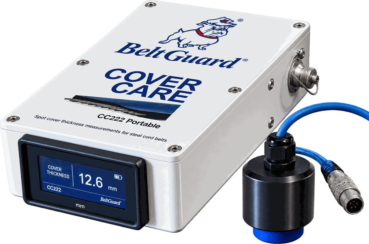
Handheld contact instrument for measuring remaining belt cover thickness. No coupling medium required.
Two Ways to Take This Further
Tell us the conveyor and we will put a system together and quote it through the appropriate Beltscan sales channel.
For engineers evaluating the system. Send us what you have and our engineering team will come back on suitability, arrangement and installation.
Send what you have — none of it is mandatory to start the conversation.